SD-WAN
SD-WAN provides secure site-to-site tunnels, LAN-to-LAN connections, exit node routing, and centralized topology management.
OOS SD-WAN functionality includes several key features:
- Site-to-Site Connection: Establishes secure encrypted connections between different sites.
- LAN-to-LAN Connection: Connects Local Area Networks across different geographic locations.
- Exit Node: Allows designating an exit node to route traffic through specific nodes.
All connections between OOS devices utilize TLS 1.3 and QUIC protocols, ensuring high security.
Site-to-site connections can be direct or configured to connect LANs between OOS devices, enabling data access across regions and networks.
Field Descriptions
| Name | Descriptions |
|---|---|
| Topology of Site | Display current site connections. |
| Add Tunnel Subnet | Create a tunnel subnet range: If node tunnel IP is set to Auto, it will be assigned from the tunnel subnet range by the OOS Controller to establish SD-WAN connections. |
| Add Site | Create a new site: Assign nodes, set exit node, tunnel IP, define neighbor connections, and add LANs. |
| Get Topology Map | View nodes within a site and their connections. |
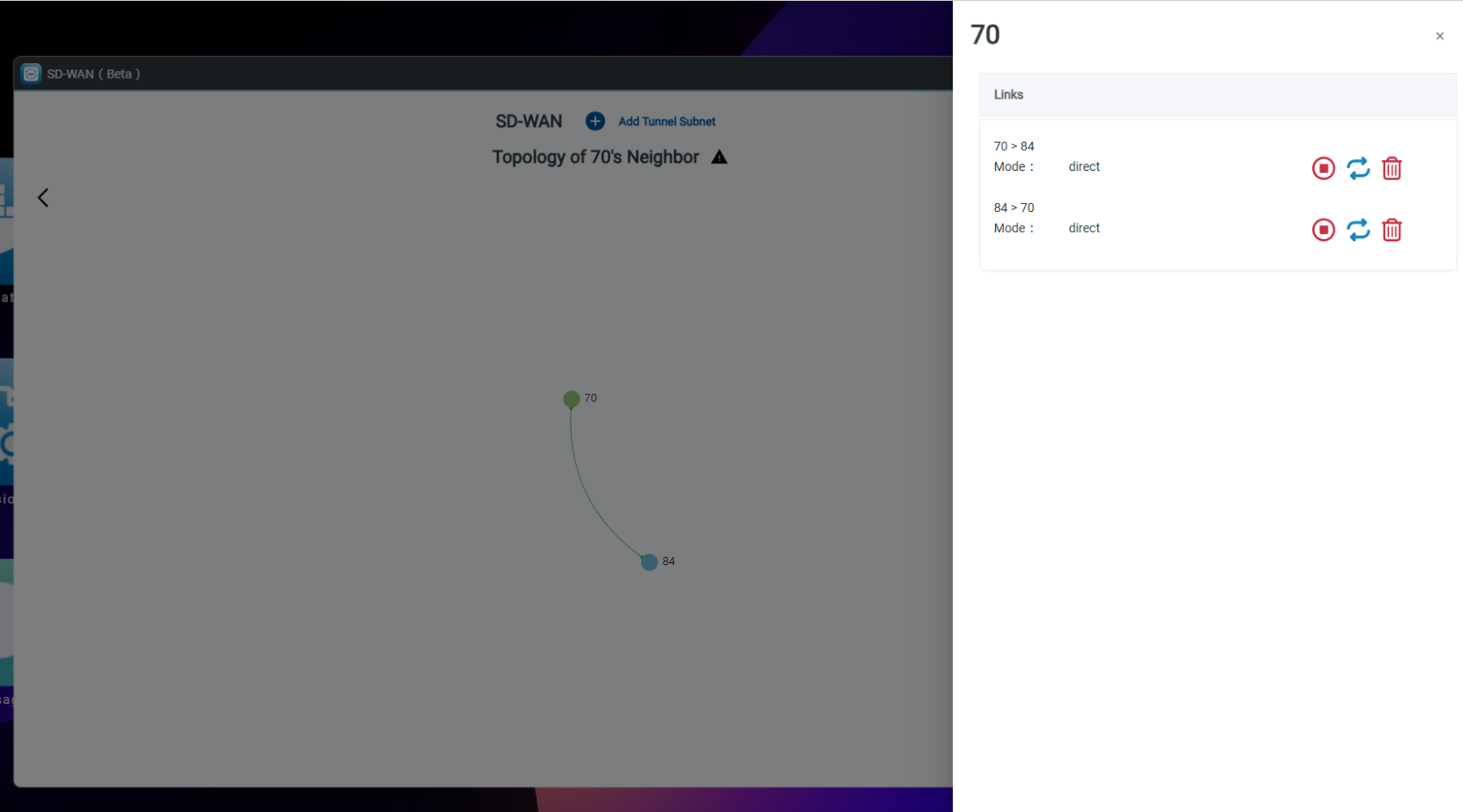
| Get Node Map | View all current connections on this OOS (node). |
| Exit Node | Designate as the exit node that handles "route to exit" OOS node traffic before forwarding it. |
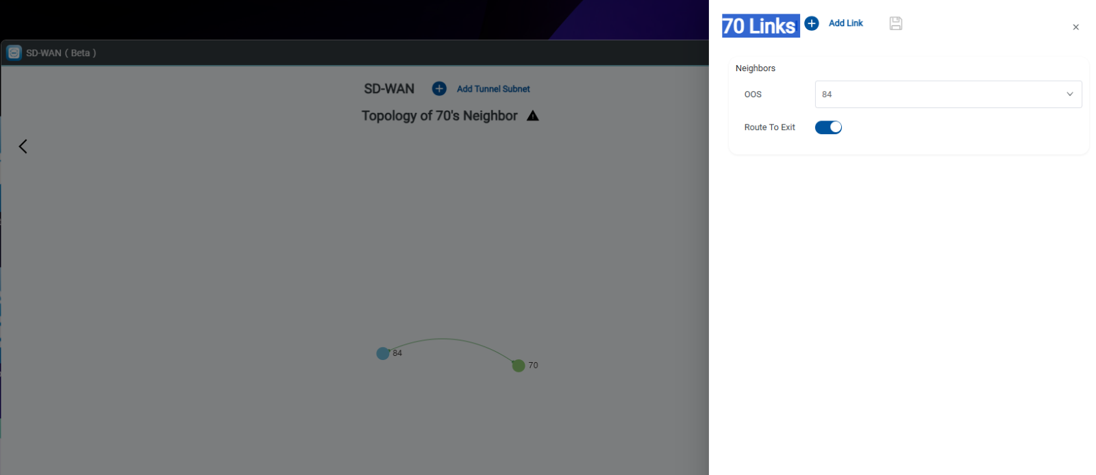
| Route to Exit | Set a node to route traffic to the designated exit node. |
| OOS's Neighbors | Select nodes to quickly build SD-WAN connections to another node. |
| LANs | Set up the LAN to allow devices on the LAN to pass through via Node or Exit Node to connect to another site. |
How to Create Site-to-Site Private Tunnels
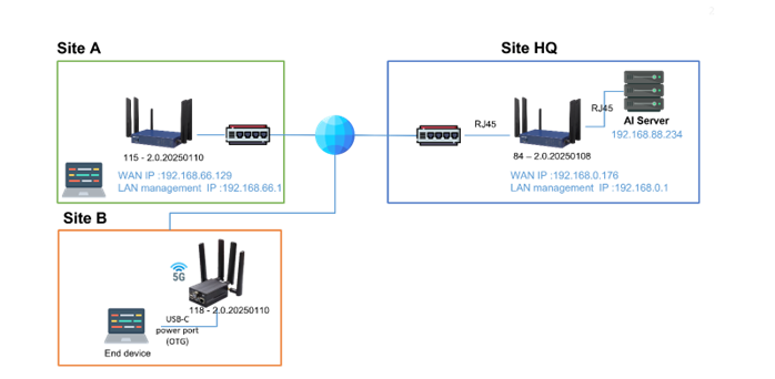
This architecture demonstrates connectivity between different company locations:
- Site A: Connects securely to HQ domain for data retrieval and AI server access.
- Site B: Portable Device powered by Type-C allows remote access to HQ domain for data retrieval and AI server access.
- Step 1: Click the SD-WAN icon.
Note: Any OOS (node) that has not established connections, or has been deleted from another site, will be moved to the "Ungroup" site. OOS nodes in the "Ungroup" site keep their SD-WAN settings. Deleting SD-WAN connections requires manual configuration.
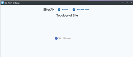
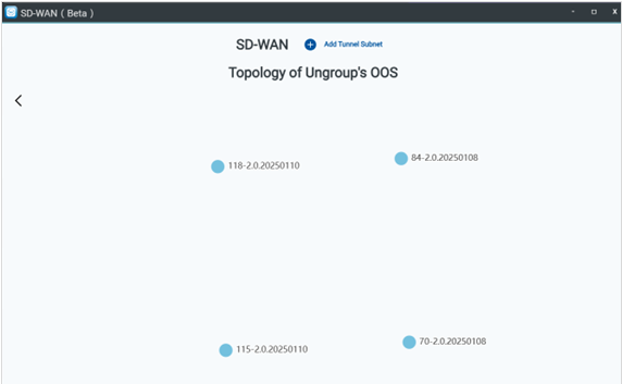
- Step 2: Click the Ungroup site, then click Get Topology Map. There are 4 OOS nodes in the Ungroup site. OOS nodes in "Ungroup" can be added to other sites. When an OOS device provisions to the OOS Controller, it joins the SD-WAN ungroup site by default to receive a tunnel IP from the default tunnel subnet.
- Step 3: Create a tunnel subnet by clicking the Add tunnel subnet icon and typing the subnet.
Note: When modifying the default tunnel IP, you must create a tunnel subnet, configure Auto mode, and select the created tunnel subnet. The OOS Controller automatically assigns OOS tunnel IPs from the subnet for site-to-site SD-WAN connections.
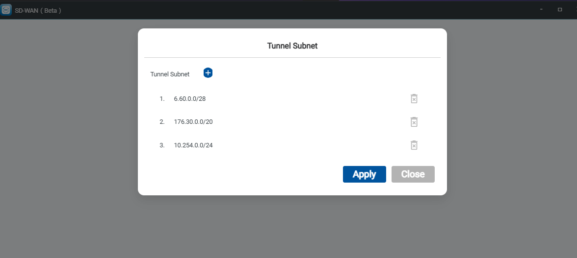
- Step 4: Create HQ site.
- Click Add Site.
- Type Site name as
HQ. - Click Add Node.
- Choose OOS (Node).
- Select Type Tunnel IP as
autoand choose the tunnel Subnet. - Select Neighbors to quickly build SD-WAN connections to other nodes.
- Add LANs: Set up the LAN to allow LAN devices to pass through via Node or Exit Node to connect to another site.
- Click the Save icon.
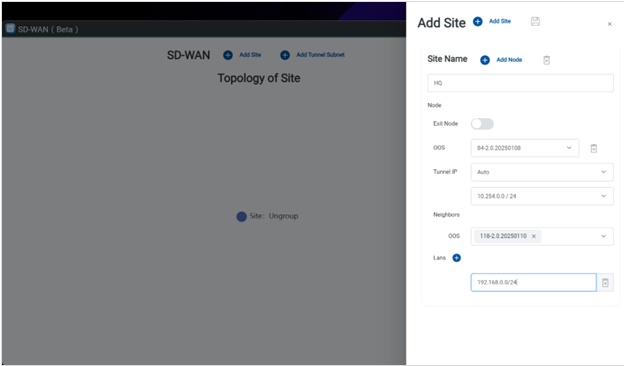
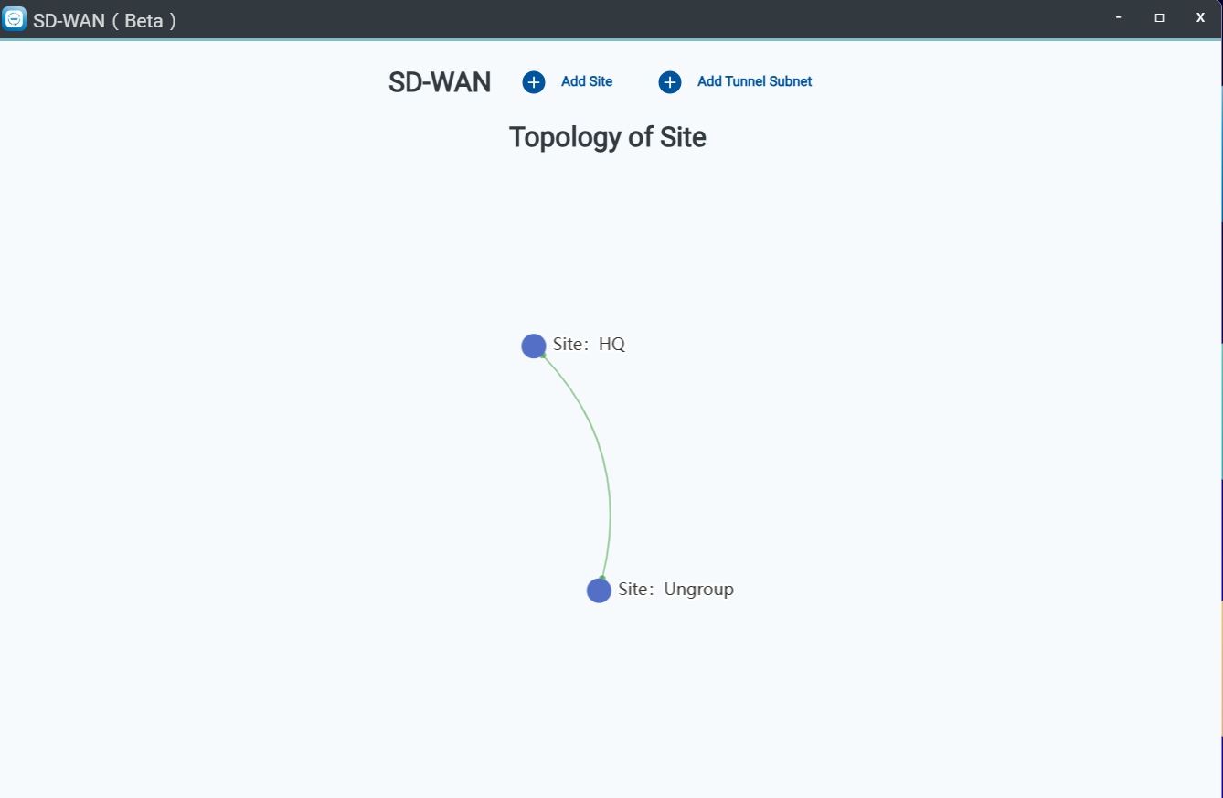
- Step 5: Create Site A by following the same procedure as Step 4.
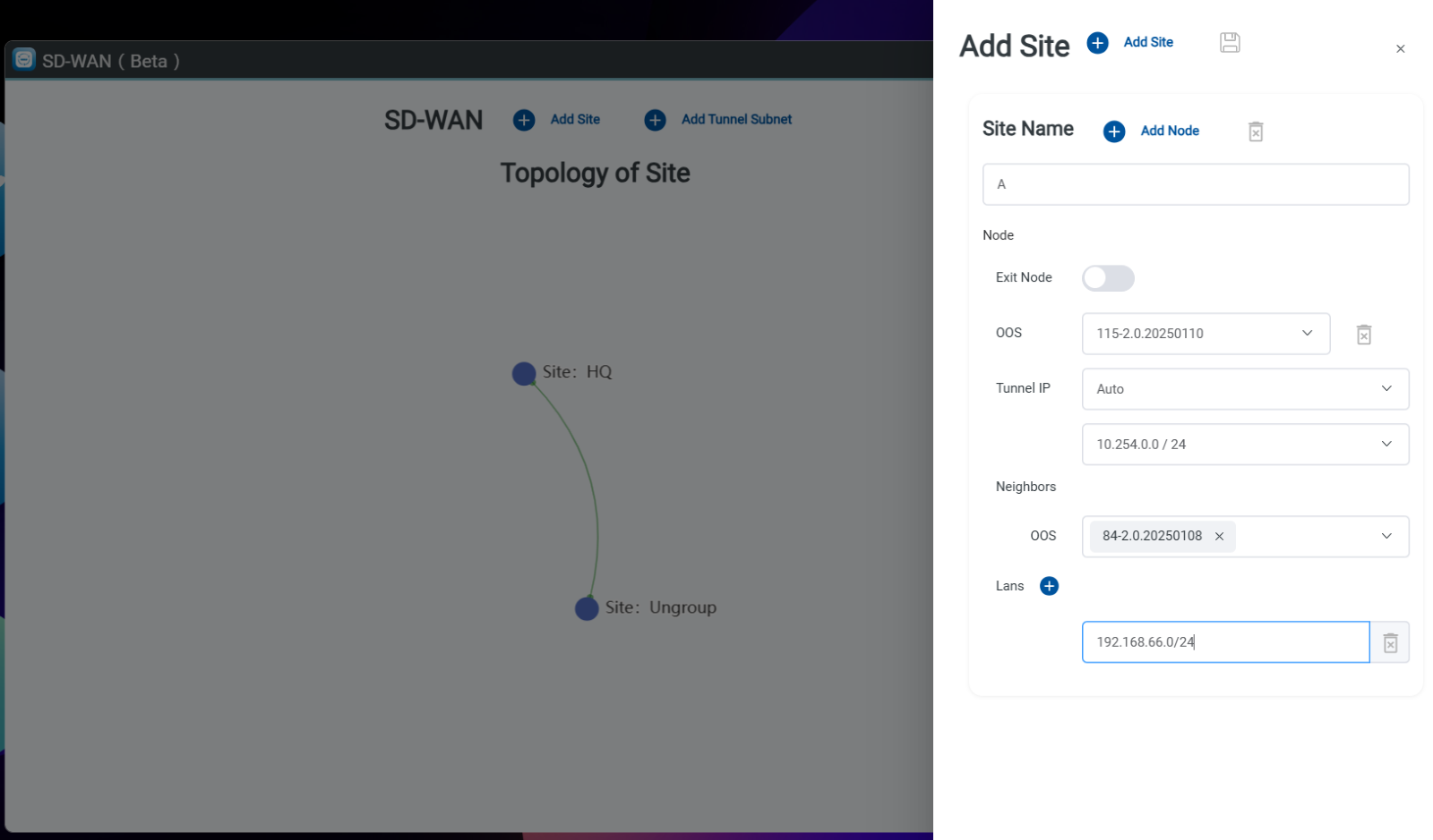
- Step 6: Connect Site A to Site HQ.
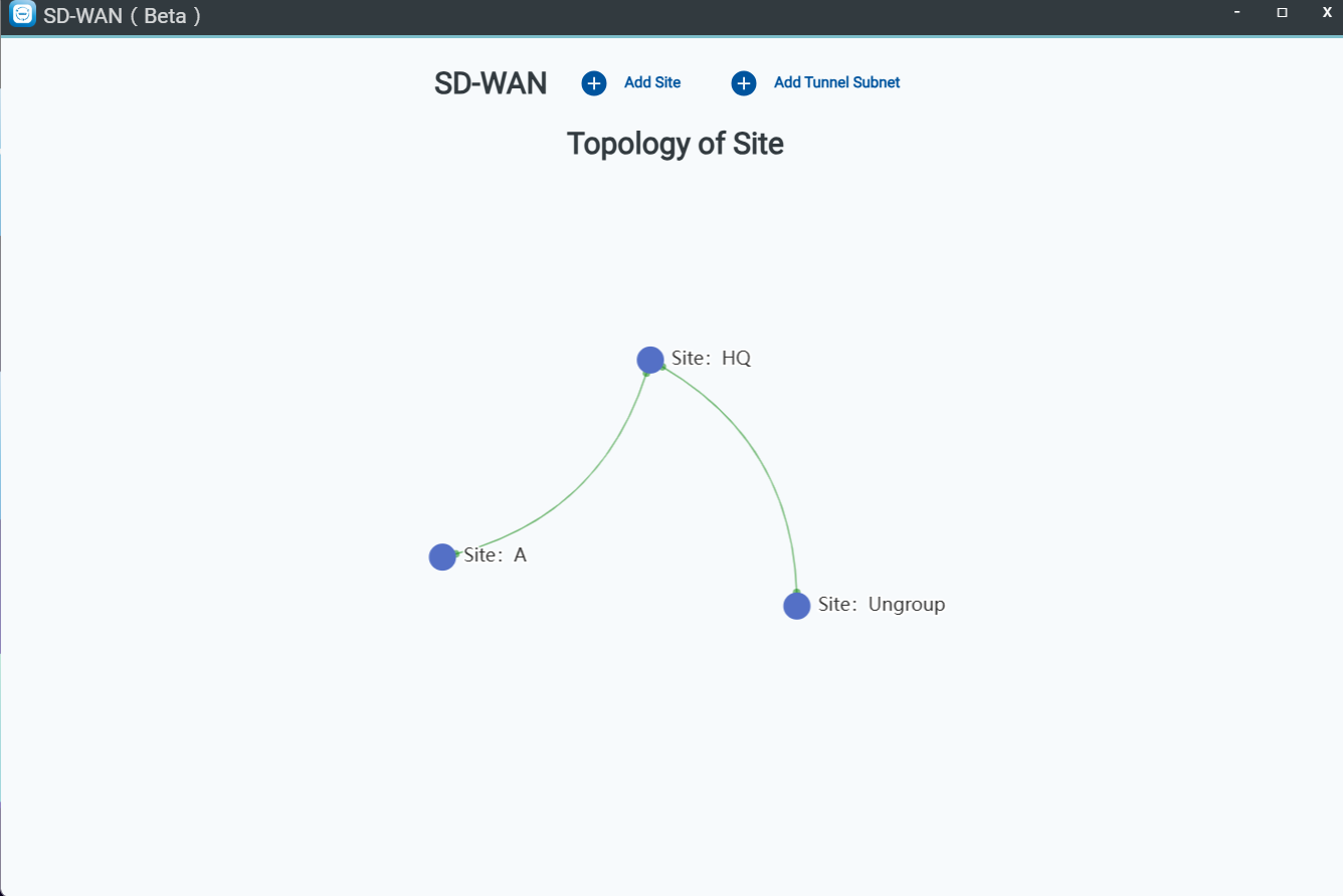
Both Site A and Site B are now connected to Site HQ.
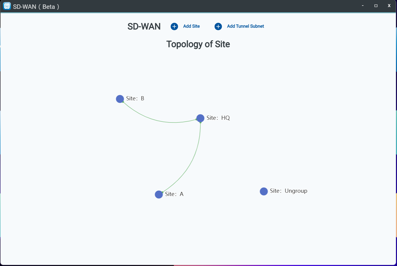
- Step 7: Click the HQ site and select Get Topology Map.
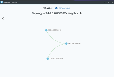
- Step 8: Click node
84-2.020250108and select Get Node Map. - Step 9: View the list of nodes currently connected to this node.
How to Set Up Exit Node and Route to Exit Node
Define an OOS (node) as the "Exit Node" and configure associated neighbor nodes as "Route to Exit Node".
This ensures all outbound traffic is directed to the Exit Node for centralized traffic forwarding.
Exit Node Configuration
- Step 1: Click the target Site.
- Step 2: Edit site to select which node serves as the exit node.
- Step 3: Click the Save icon.
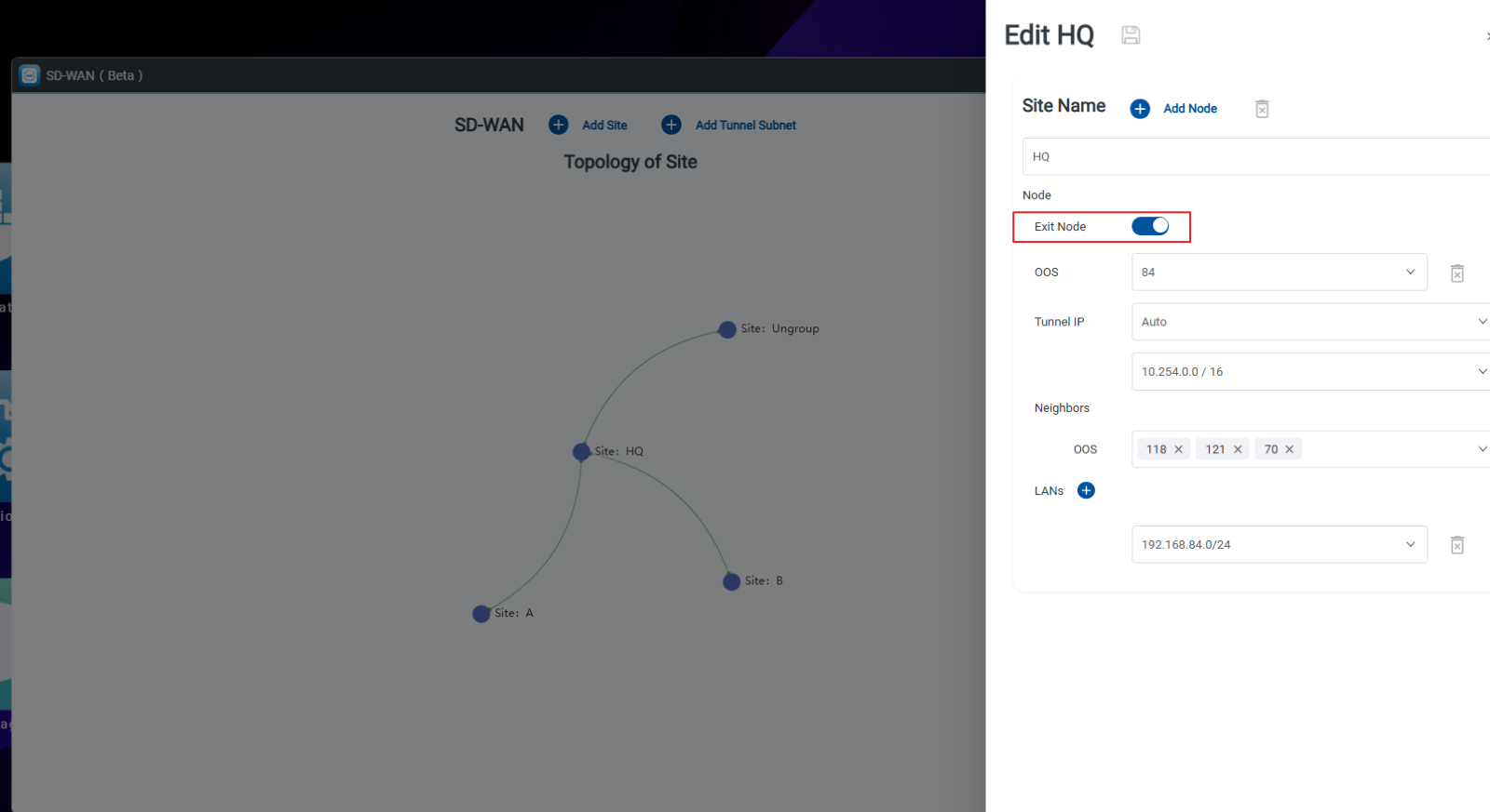
Route to Exit Node Configuration
- Step 1: Click the target Site.
- Step 2: Click Get Topology Map.
- Step 3: Click the node.
- Step 4: Select Get Node Map and click the Edit icon.
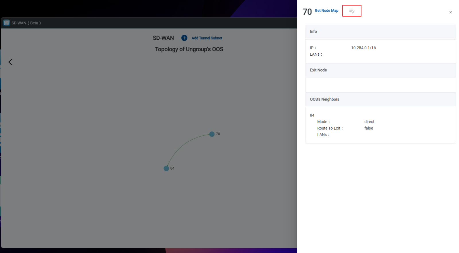
- Step 5: Toggle Route to Exit.
- Step 6: Click the Save icon.
How to Edit, Stop, Restart, or Delete Node Connections
Manage node connections using Stop, Restart, or Delete:
- Step 1: Click the target Site.
- Step 2: Click Get Topology Map.
- Step 3: Click the node.
- Step 4: Select Get Node Map.
- Step 5: Click the link between nodes.
- Step 6: Manage node connection options: stop, restart, or delete the connection.